Lab 8 - Pitch and Yaw Camera
The base code for this lab can be found on GitHub here
This assignment is due on Friday 3/2.
But, only the Camera aspects are due on the due date.
The remaining FBO aspects are due on Wednesday 3/7.
Objective: implement pitch and yaw and play with FBO effects.
Orientation
Your main task is to implement a pitch and yaw camera using the MatrixStack lookAt function to control the virtual camera.
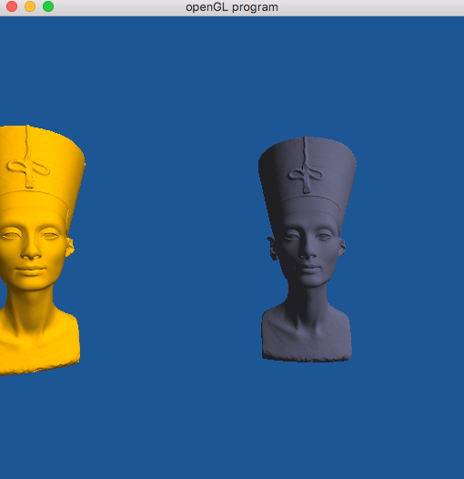
The base code includes a scene with several models positioned in a circle around the camera.
Try using the a and d keys and you will see that the camera can rotate in Y to look around at the models.
There is also an interesting image based effect that if you click the mouse and scroll the scene will rotate in Y and the models will look blurry (more on this in task 2).
Task 1
Write code for a pitch and yaw camera. We will be using the lookAt function included in the MatrickStack to control the view matrix. Please adjust your code (including your vertex shader) to include a view matrix and pass the matrix created by the lookAt function to your shader for use as the view matrix.
1)
Use glm::lookAt to generate a view matrix.
Replace the global rotation with this matrix and test the functionality.
2) Now use mouse input to control the pitch and yaw of where the camera is looking. Keep the eye position fixed and modify the “look at” point.
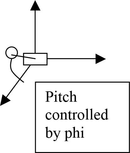
3)
Pitch will be controlled by the angle phi, map this to the y motion of the mouse.
When the user clicks and drags, this motion changes the angle.
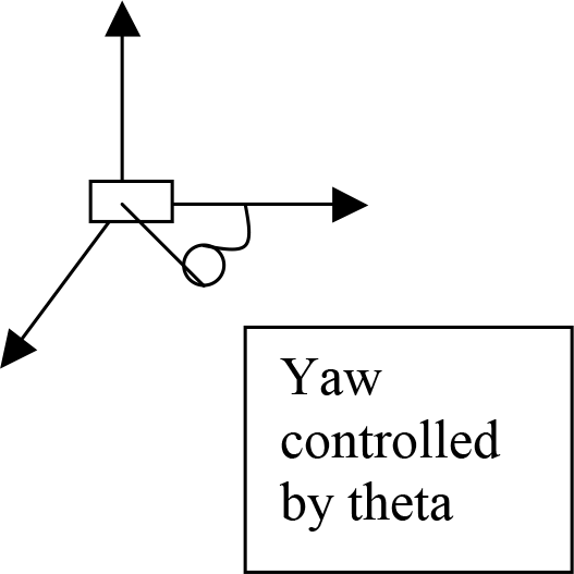
4)
Yaw will be controlled by the angle theta, map this to the x motion of the mouse
When the user clicks and drags, this motion changes the angle.
Given a pitch and yaw angle, you can compute the ‘look at’ location by:
x = radius*cos(phi)*cos(theta)
y = radius*sin(phi)
z = radius*cos(phi)*sin(theta)
Please carefully think about what phi and theta should start out as,
and for coding, convert the degrees to radians (if necessary).
Think about how phi and theta should change as you continue to move the mouse and “look around.”
Task 2
Notice that in the base code there is a variable Moving that when set,
changes the render of the scene to appear blurry.
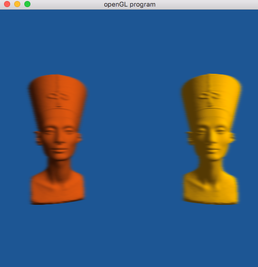
This is making use of first rendering to a frame buffer object (think of this as an image of the rendered scene) and then texturing that data onto a quadrilateral, but first processing the input image by computing an image blur (only in the horizontal direction).
Look at the code in main.cpp and the associated shaders to make sure you understand what is happening.
Next replace the current effect with an alternative effect:
- motion blur
- Gaussian blur
- a bloom effect
- or any other creative effect to show you understand the process).